
Normally, as a DJ, you have tons of cables in your toolbox. Last week, however, I ran into the problem of connecting a device with a balanced XLR input to my setup, which has an RCA output (phono jack). Finding suitable cables for this isn’t so easy; a bit of DIY is required, so it’s time to fire up the soldering iron. I usually make my own cables unless there’s a good-quality, off-the-shelf option available at a reasonable price. So here’s a little tutorial on making your own complex cables. It’s not directly related to tango, but we DJs do have a responsibility!
Before we begin, a few preliminary remarks about cable connections. In the hi-fi sector with consumer devices, an output signal is transmitted via a two-wire cable. One wire is connected to ‘ground,’ which is the usual reference potential. The other wire carries the audio signal, which is an alternating voltage signal with a maximum amplitude of 2 volts (RMS). This level is referred to as line-level audio. Such a two-wire cable is described as ‘unbalanced.’
My current DJ mixer outputs the signal via two RCA (Radio Corporation of America) coaxial connectors, one each for the left and right channels. Even though the cable is coaxially shielded in this case, long cable lengths are extremely problematic because interference signals, such as hum, often become noticeable.
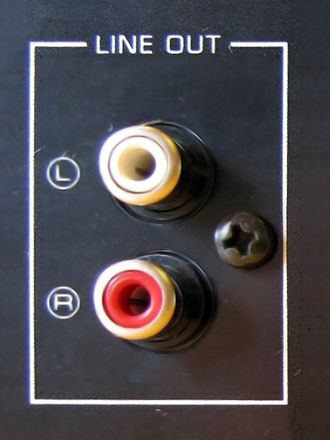
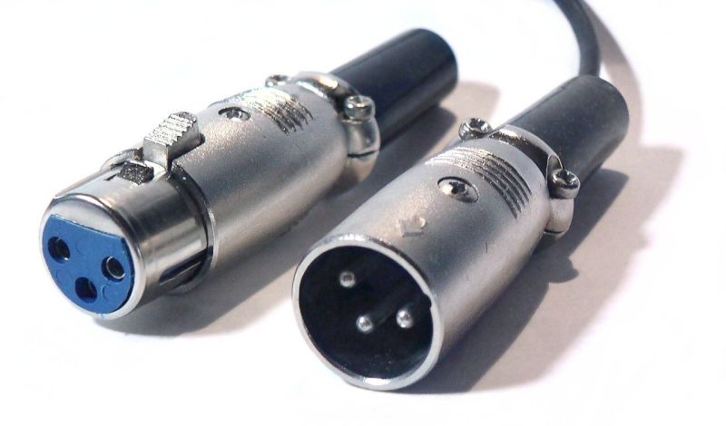
Fig. 1: RCA sockets (left), three-pin XLR connector (right).
In professional settings, balanced transmission methods are often used, where the signal is transmitted over three lines. These consist of a ground line, a line for the signal (+ or ‘hot’), and a second line (- or ‘cold’) for the inverted signal. This principle allows for the simple elimination of interference in the cable by electronically combining the two signals. Those interested in the ingenious technique used should research it further online. This makes cable lengths of many meters (10-100 meters) possible without any interference.
In semi-professional settings, connectors with three connection pins are often used for this purpose, e.g. the so-called XLR connector, although connectors with more pins are also common.
To transfer an unbalanced signal, such as from my mixer, to a professional device like my equalizer with a balanced input, you would normally need a special device that electronically generates the balanced signal (a so-called DI box, DI = ‘Direct Inject’). However, a somewhat unconventional solution is to feed the signal into the positive input and simply connect the negative input to ground. This has two disadvantages: the cable is unbalanced and therefore susceptible to interference, and since only one input is used, only half the voltage difference is present at the balanced input. For short cable runs, however, this is acceptable; only the signal level needs to be adjusted.
Here is a description of my crafting process:
You will need an XLR cable (coaxial cable with two inner conductors), two XLR connectors, and two RCA connectors. In addition, you will need a good quality soldering iron (preferably a temperature-controlled soldering station), some pliers and other electrical tools (Fig. 2), and a multimeter for final testing.
A small table vise helps to hold the connectors in place during the soldering process. I often use pliers and a rubber band (Fig. 3)..
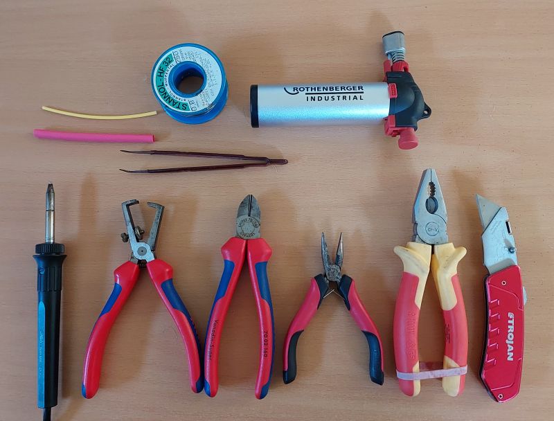
Fig. 2: Tool for working on the cable.
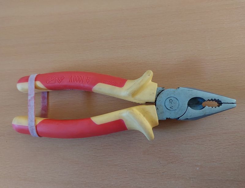
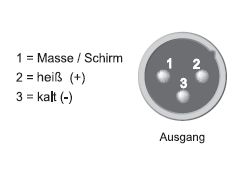
Fig. 3: Pliers with a rubber band serve as a vise (left). Pin assignment of the XLR connector (right).
Preparation: Cut the cable to length, strip the outer insulation, untangle the braided shield, and twist it together. Then strip the inner conductors as well and apply solder to all three cable ends (Fig. 4). The lengths should be measured so that the cable will later sit correctly in the connector’s clamping mechanism. Don’t forget to slide the connector housing over the cable beforehand.
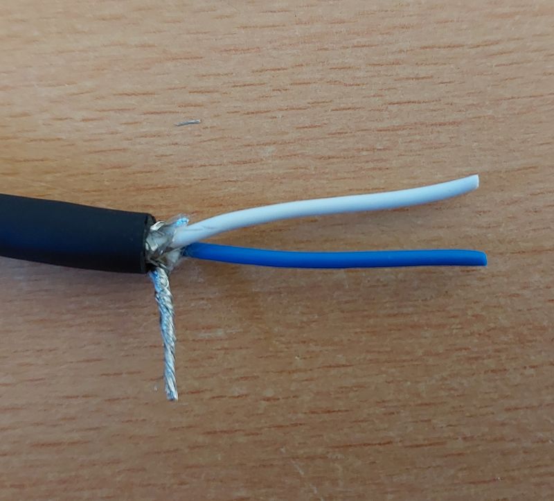

Fig. 4: Cut cable to length and twist the outer conductor (left). Cut further and tin (right)..
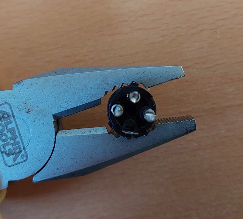
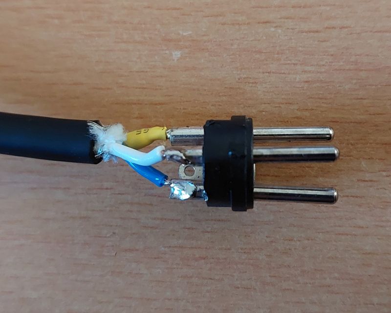
Fig. 5: Preparing the connector (left) and soldering the cable (right).
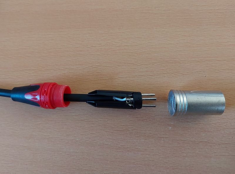
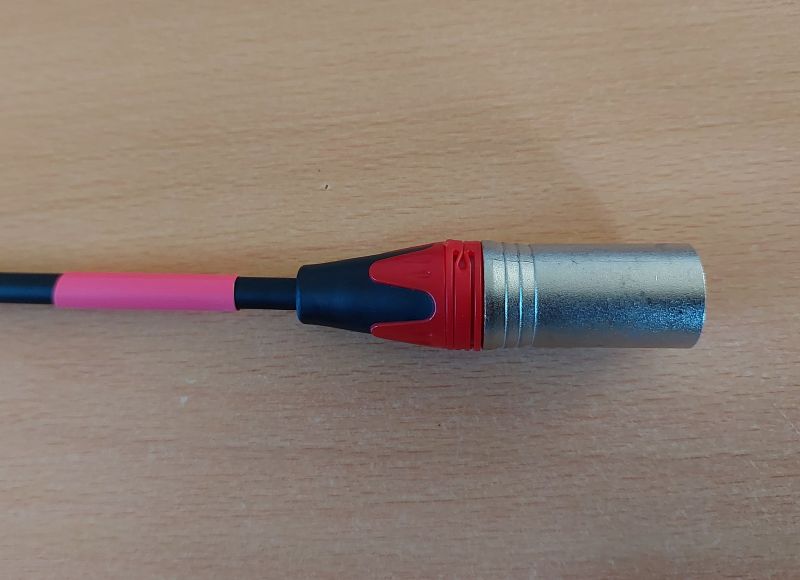
Fig. 6: Assemble and screw together the connectors. Apply a red mark..
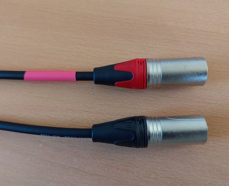
Fig. 7: Both XLR connectors are finished
Soldering: First, solder the ground wire to pin 1. I’m using a little heat shrink tubing here to protect the bare wire braid. Then solder one wire to pin 2 (+), the blue wire in the picture, and the other wire (the white wire in the picture) to pin 3 (Fig. 5). Use very little solder and only enough heat to avoid damaging the wire (here, the Ersa soldering station is set to 310 degrees Celsius).
Finish: Assemble the connectors and ensure the strain relief is working. Although the connector shown in the picture is color-coded (red = right), I’ve made it a habit to add another color marking in front of the right-hand connector, here using red heat-shrink tubing (Figs. 6 and 7). In racks with many devices and XLR connectors, this additional color marking is very helpful, especially since not all XLR connectors are color-coded (Honestly, this one connector is the only one with a red color marking that I’ve ever owned).
Now let’s move on to the RCA connector, which is a bit more difficult to solder. Here, we will also connect the negative signal wire directly to ground.
Preparation: Strip the cable and twist the live conductors together. Strip the negative wire completely and connect it to the ground wire (Fig. 8). It’s important that the twisted end of the wire still fits through the small hole in the connector. Cut the signal wire to length, strip the insulation, and tin the ends. To ensure the correct length, hold the connector next to it (Fig. 9). Don’t forget to attach the connector housing to the cable beforehand – the right way round!
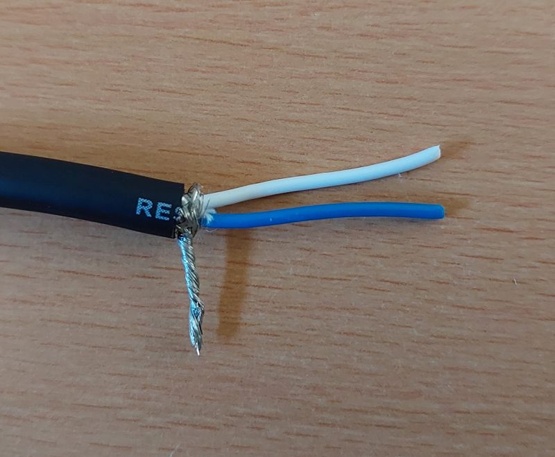
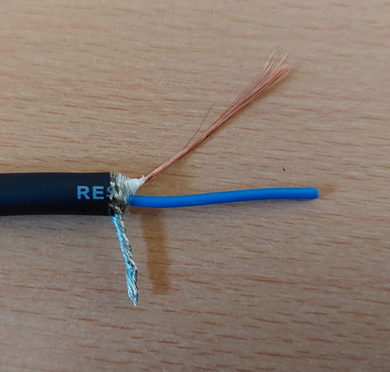
Fig. 8: Preparation. Completely strip the insulation from the (- /Cold) connection and connect it to ground.
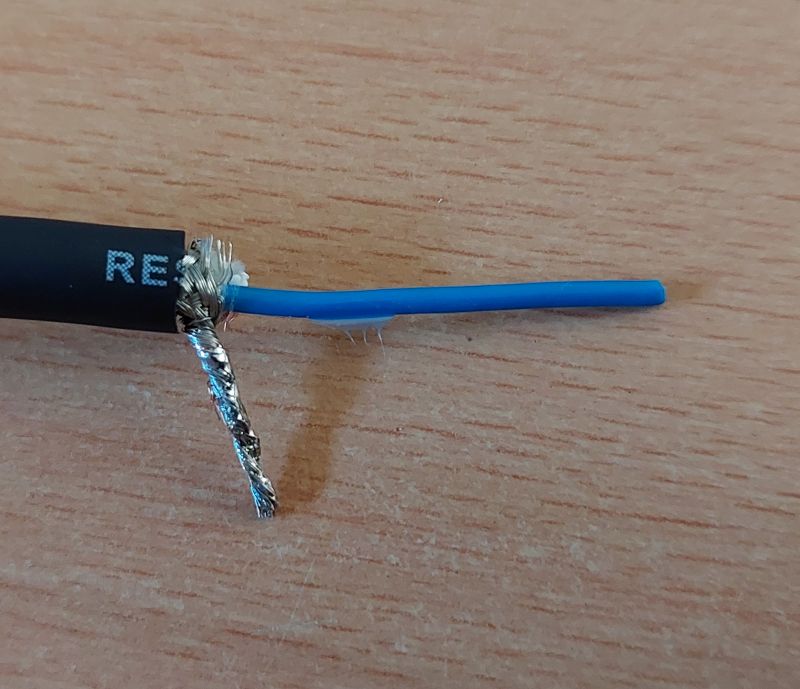
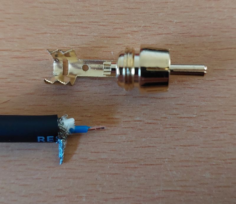
Fig. 9: Tinning and cutting to length according to the plug
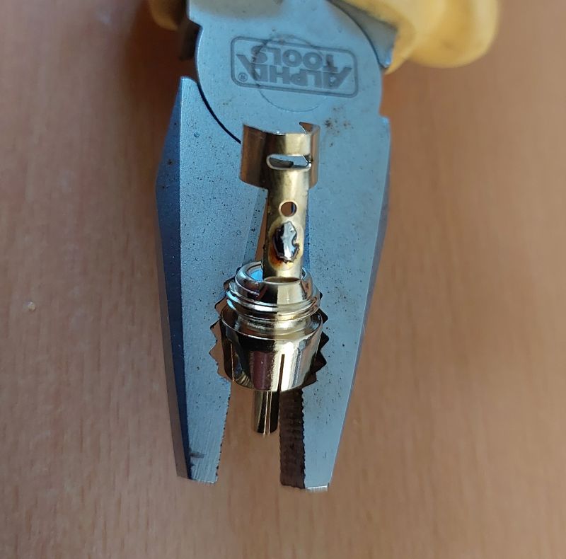
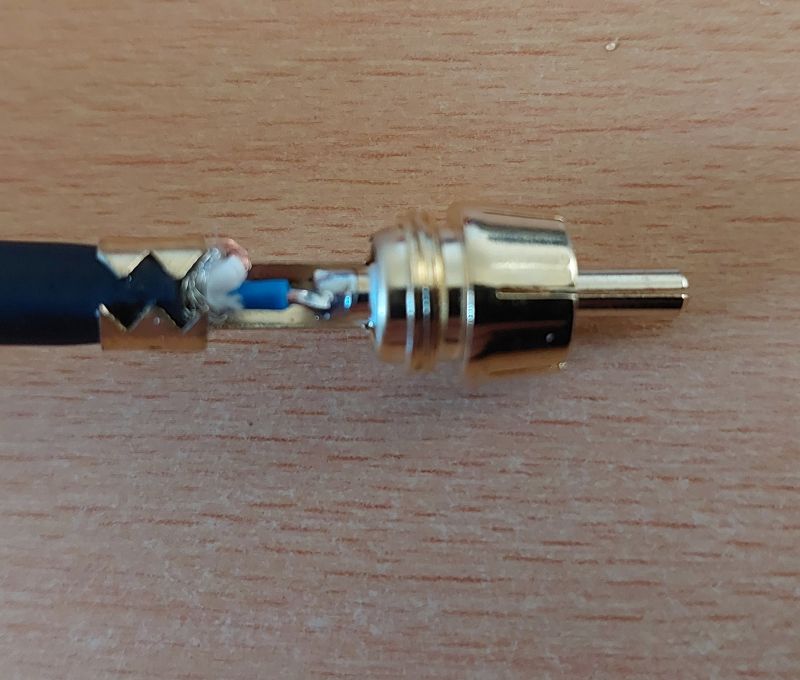
Fig. 10: Tinning the connector (left), first soldering the signal wire and crimping the cable (right).
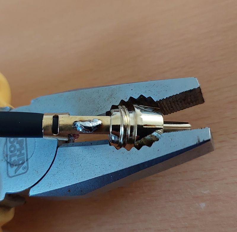

Fig. 11: Now pull the ground wire through the small hole and solder it. Screw the connector together..
Anlöten: Now tin the connector. Pull the ground stub through the small hole and insert the signal cable into the receiving hole of the inner connector (Fig. 10). Crimp the cable firmly before soldering and then solder both connections, again using solder as sparingly as possible (Fig. 11).
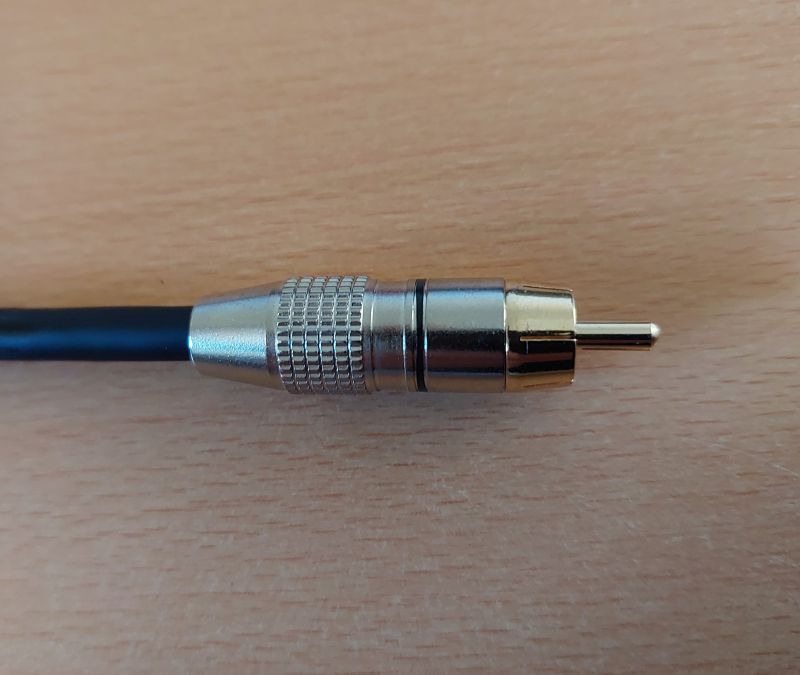
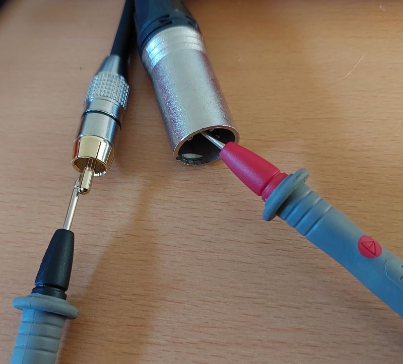
Fig. 12: Assembled connector (left). Checking the contacts with a multimeter (right).
Completion and final inspection: Screw the connectors together. Perform a final check using a multimeter as a continuity tester (Fig. 12). Pin 2 on the XLR connector should make contact with the RCA inner connector. The ground ring of the RCA connector should be connected to pins 1 and 3.
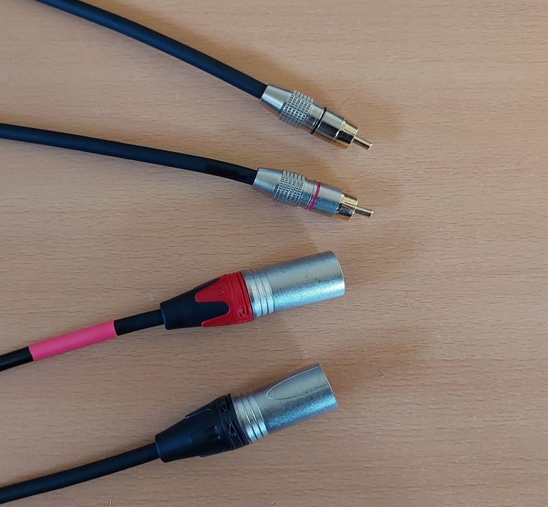
Fig. 13: The finished connection cables: RCA unbalanced to XLR (balanced).
The two cables for left and right are now complete (Fig. 13).
Finally, a word of advice: use only top-quality materials (in this case, gold-plated RCA connectors) and always have some cable and connectors on hand in your toolbox..
Have fun trying it out!
-Richard (VK4WRS)